In part 1 of this series I described the design of my HiFimeDIY T1 wooden case project and finished most of the fundamental parts of the chassis. In this segment I continue with the back panel where the connectors are mounted.
The connectors are, unsurprisingly, designed to be mounted in a thin metal chassis and therefore have quite short screw threads. The sides of the pre-made case I used are 6 mm solid wood, much too thick for the connectors. To mitigate this I opted to cut out a large part of the back and mount a thinner piece of plywood on top, which I could mount the connectors on.
I started by sawing a suitable piece of 3 mm plywood and marking the holes on masking tape. The masking tape was somewhat unnecessary but enabled me to make a bigger mess while marking without having to clean up the wood afterwards.
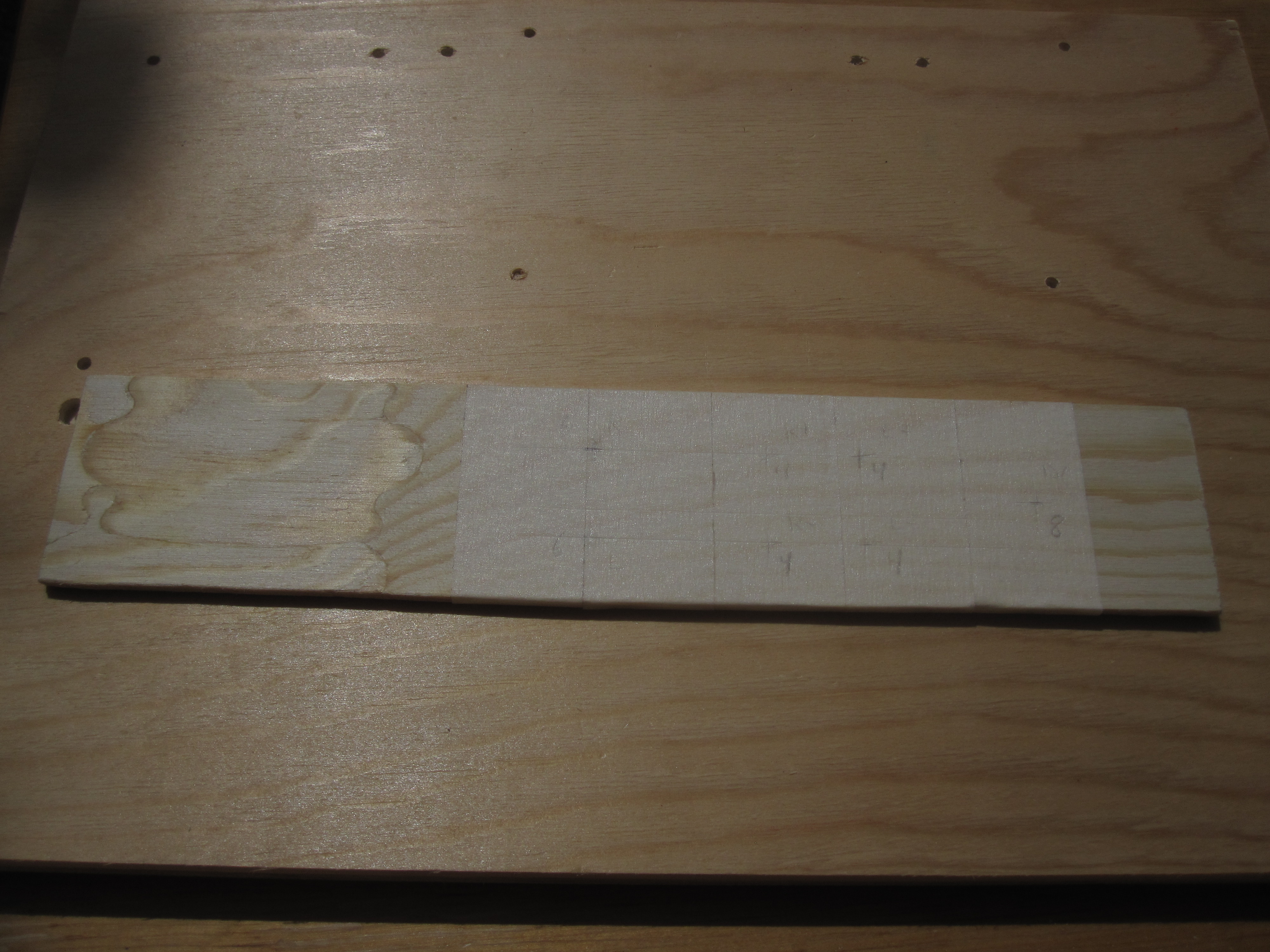 |
With the holes drilled and the connectors test-fitted it looked like this:
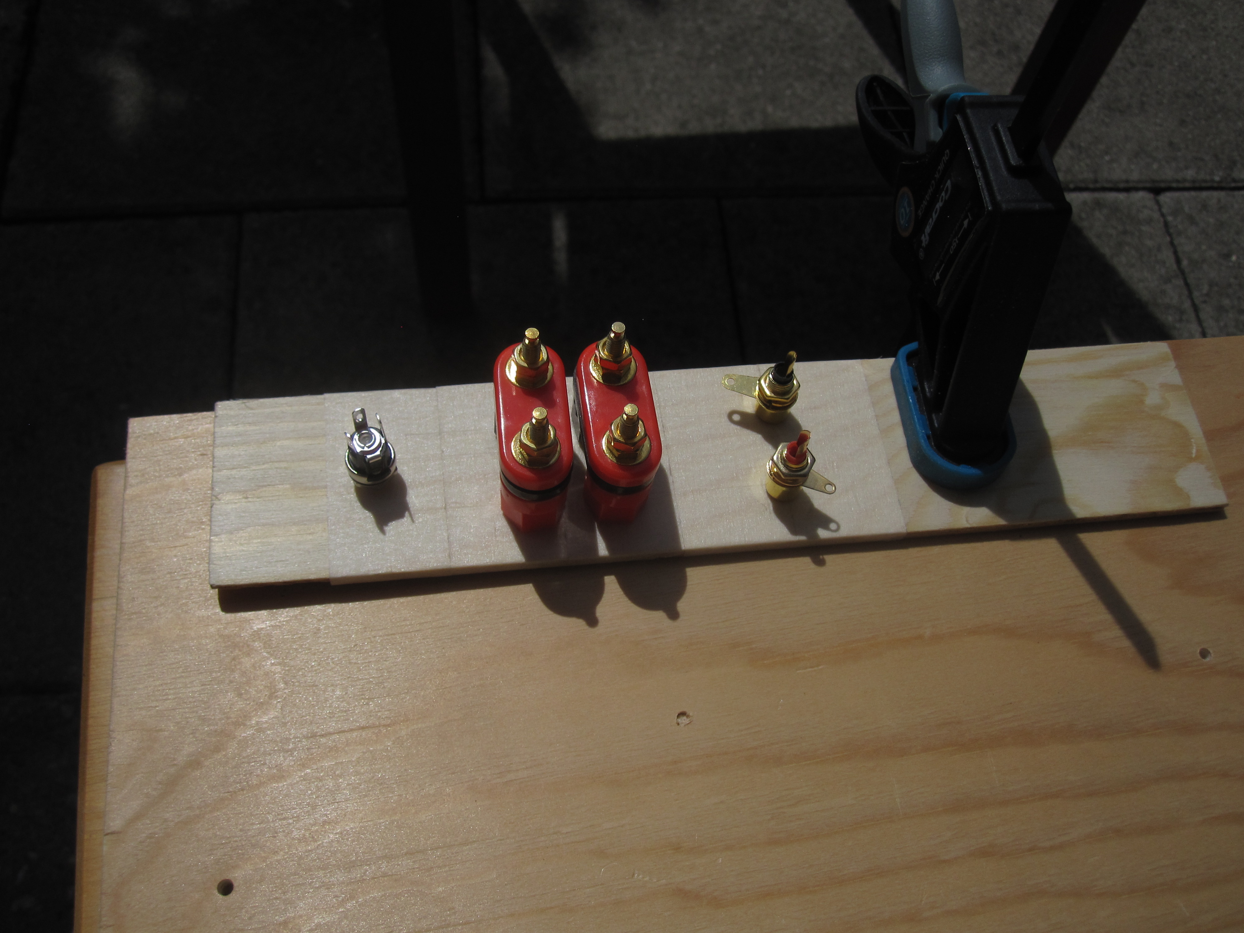 |
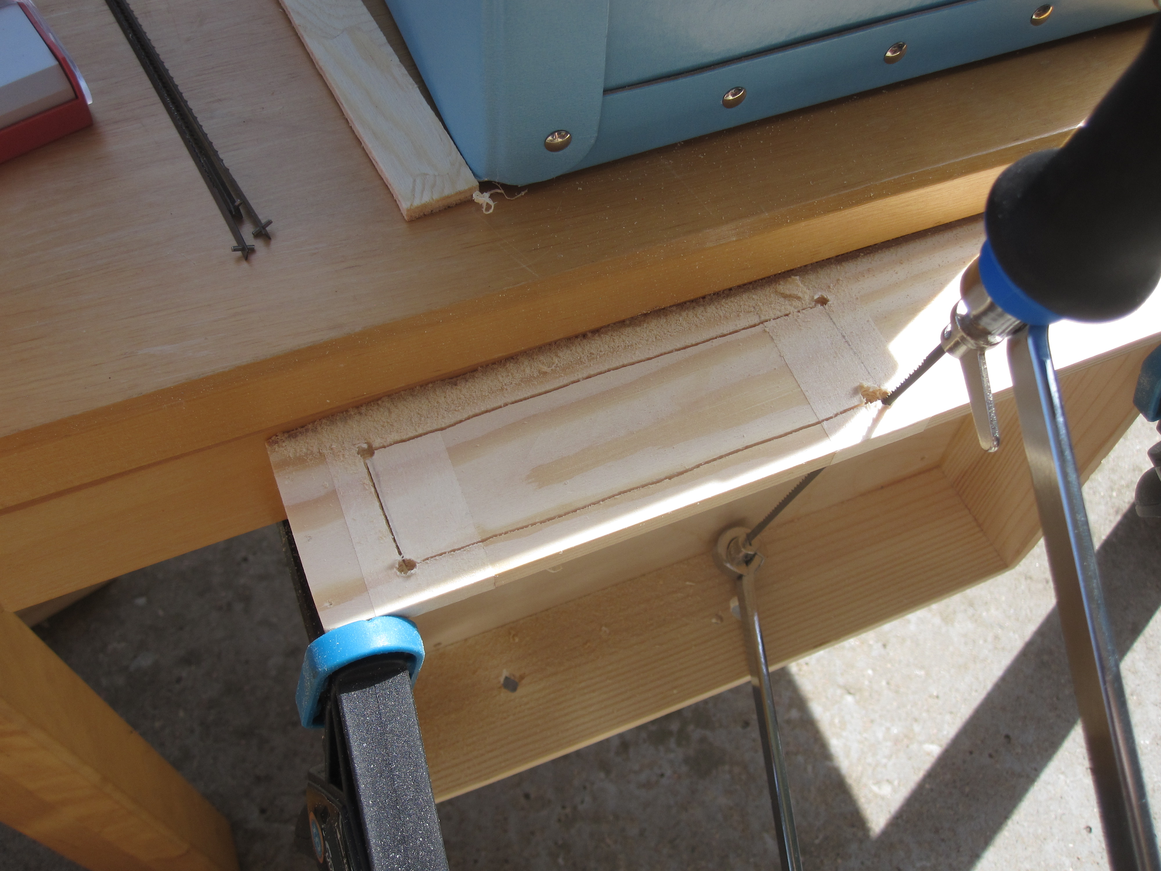
Then I had to make a rather large cut out in the box. I marked out a rectangle, drilled holes in the four corners and put the saw blade through one of the holes. The jigsaw worked great for this job.
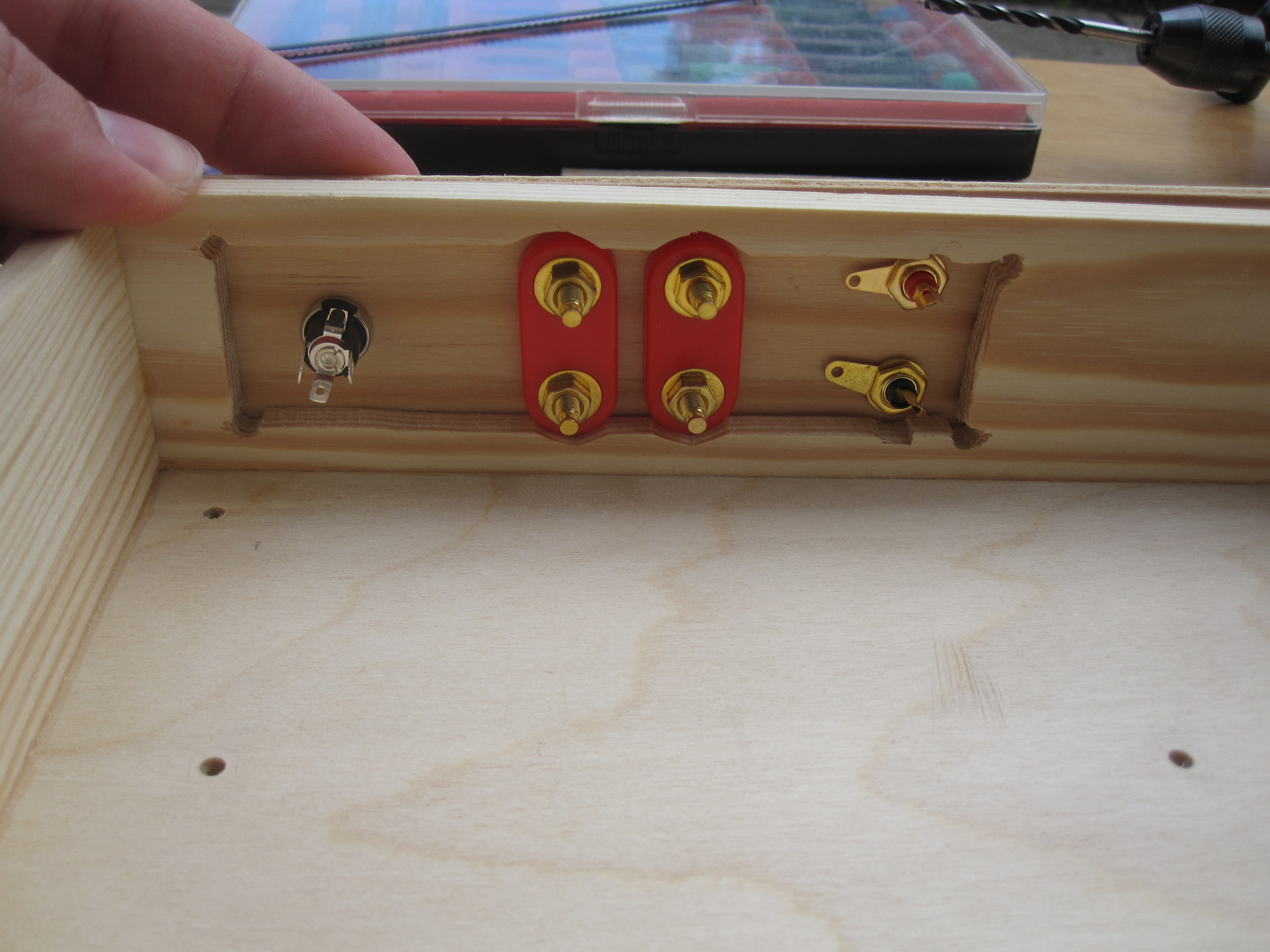
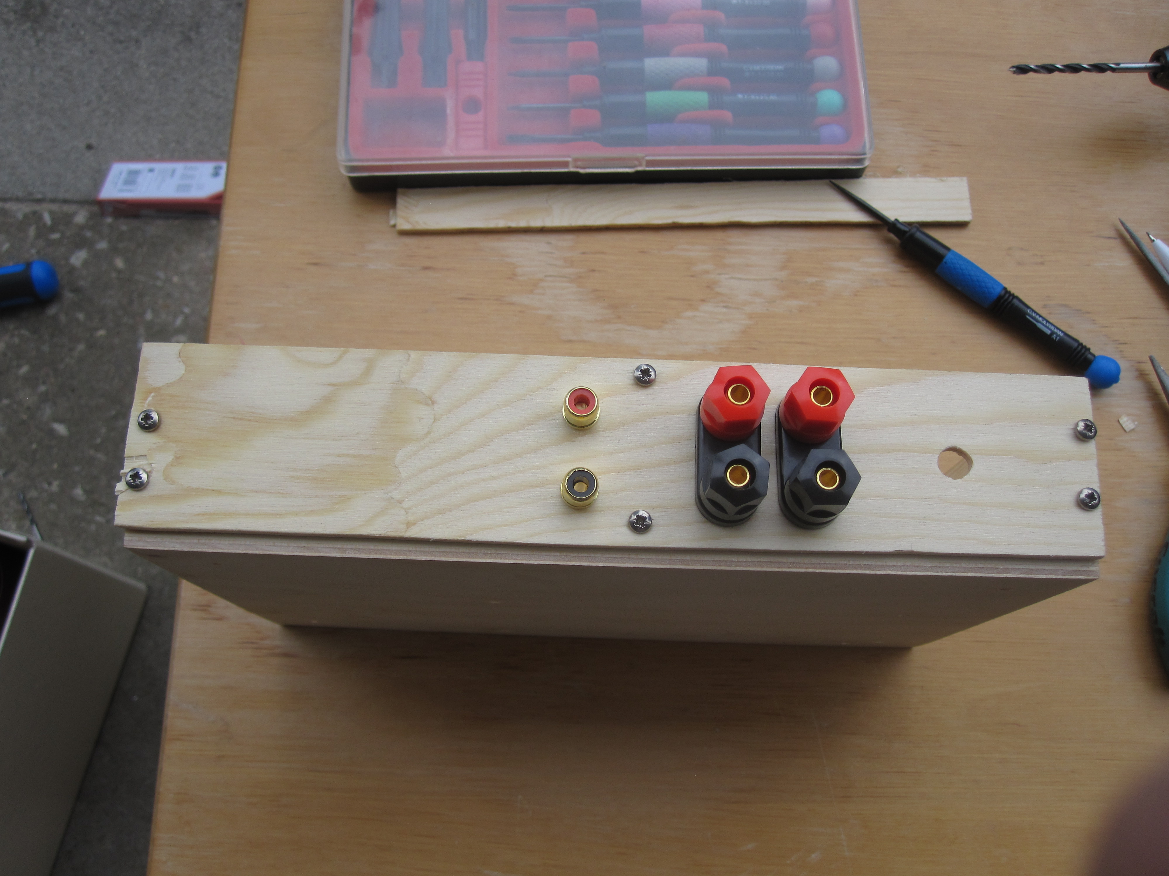
I had to carve out some additional space for the large speaker connectors and the RCA input jacks. This is how the back panel ended up:
I mounted it on the case using sheet metal screws, since they were the only ones the hardware store offered in a suitable size. To avoid hitting the nails that hold the case together I had to place the screws somewhat asymmetrically.
The screw mounted rubber feet I also got from Clas Ohlson. These are actually intended for furniture but I found them to be excellent appliance feet as well.
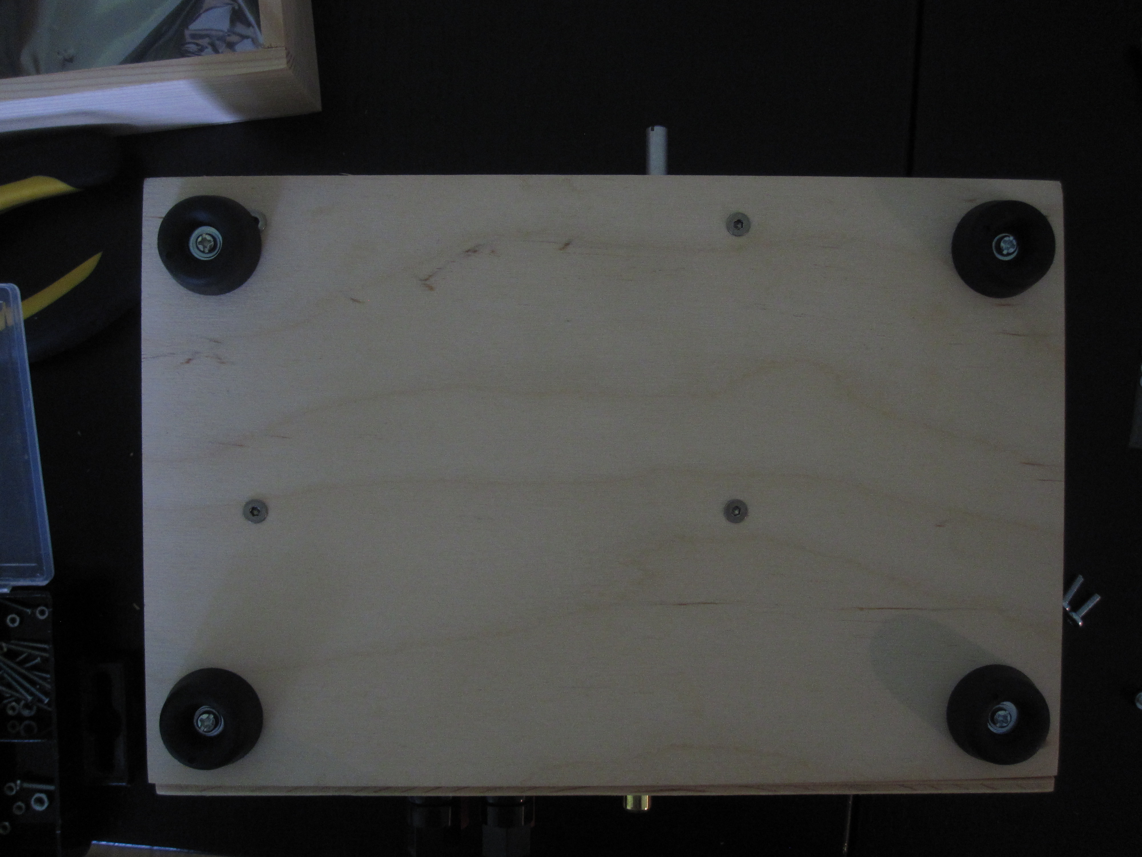
As you can see in the top left corner I made the rookie mistake of not accounting for the appliance feet when I laid out the screw holes on the bottom of the case. Fortunately, the screws holding the PCB are countersunk so the overlap didn't cause any issues.
Finally, here is the finished amplifier with the cover off:
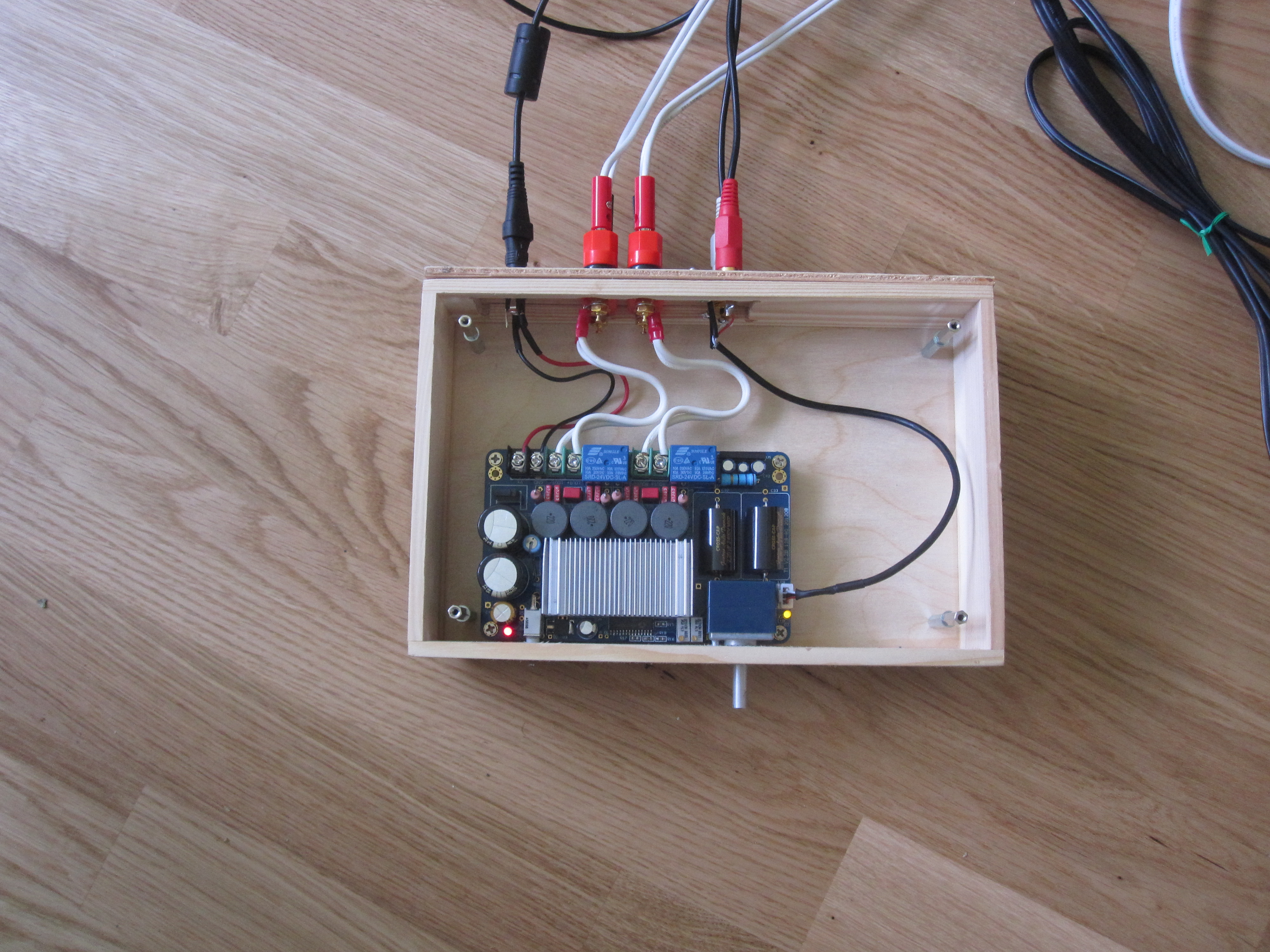
With the top cover on I used the amplifier for a few days to see if it worked and if I was satisfied with it. As the case would be completely shut I was a bit worried about heat dissipation. I borrowed an infrared thermometer from a friend to measure the amplifier temperature. After running it for an hour or so I found that the hottest parts on the board, the output inductors, reached about 50-55 °C. I think this is a bit on the hot side, considering that I might want the amplifier to remain functioning for tens of years if I like it. So I came up with a cooling solution, which I will describe in the next segment.
Update 2019: I never did write that followup segment. The cooling solution consisted of a grid of holes drilled in the top and bottom above the heatsink on the amplifier board. I'm not sure what difference it made in practice but in any case the amplifier has been working well for two and a half years now. I also oiled the outside of the wooden box to make it easier to keep clean. I've been quite happy with this project!