Refer to Looking for a new hifi amplifier for background to this article.
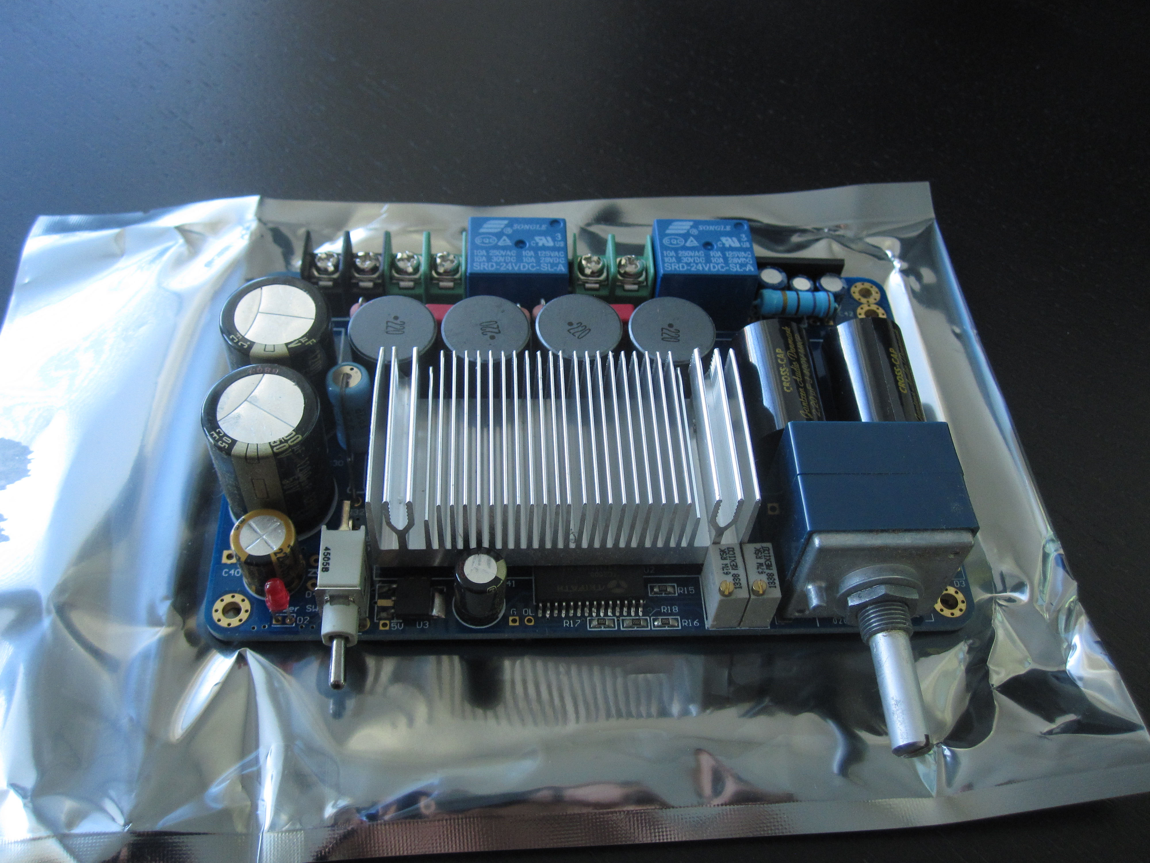
So I bought a T1 from HiFimeDIY. Shipping was reasonably priced and fast as the parcel was shipped from Belgium. I took some close-up pictures of the board when I received it, shown in the image gallery below.
HiFimeDIY T1 unboxing album on Imgur
Noteworthy:
- The volume potentiometer is somewhat dirty, unlike the rest of the board. There are no signs of wear on it though.
- Through-hole parts look hand-soldered. Soldering joint quality looks decent to me, although there are flux stains left on the board that should have been cleaned.
I will eventually build a proper enclosure for the amp, but for now I just want to quickly wire it up to ensure that it is not DOA.
Power supply
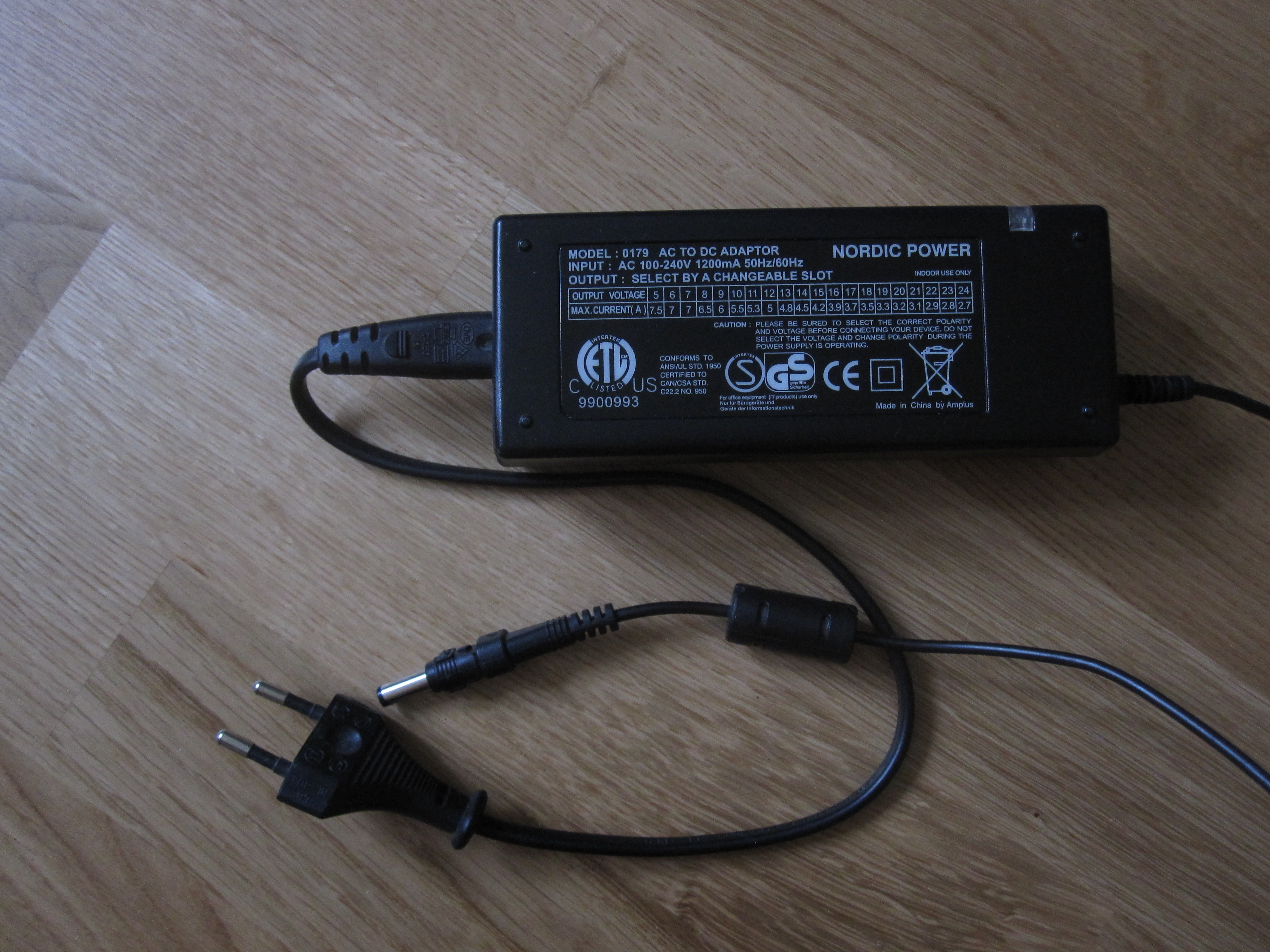
The T1 can be powered by a 24-39 V regulated DC power supply. Higher voltages allow for higher power output. Since a high voltage, high current power supply is neither a common household item (even in the home of a tech geek), nor something regularly found in electronics trash, they are kind of expensive to buy. As I am not planning to run the amplifier anywhere near its limit (since that would probably blow the windows right out of their frames in my small apartment), I figure that my adjustable 70 W power supply will do for now. It can go up to 24 V which is just enough for this amp. Every electronics geek should own an adjustable power supply. They come in handy in lots of situations. I regularly use mine for testing old electronics junk that I get a hold of.
 |
Cabling
The input is connected to a 3-pin JST connector. A short cable with JST connector on one end is included in the kit.
My first attempt at wiring it up consisted of aligator clips, 2.54 mm jumpers shoved into the JST connector, and bare wires wedged into the power supply connector using needles. See the pictures below.
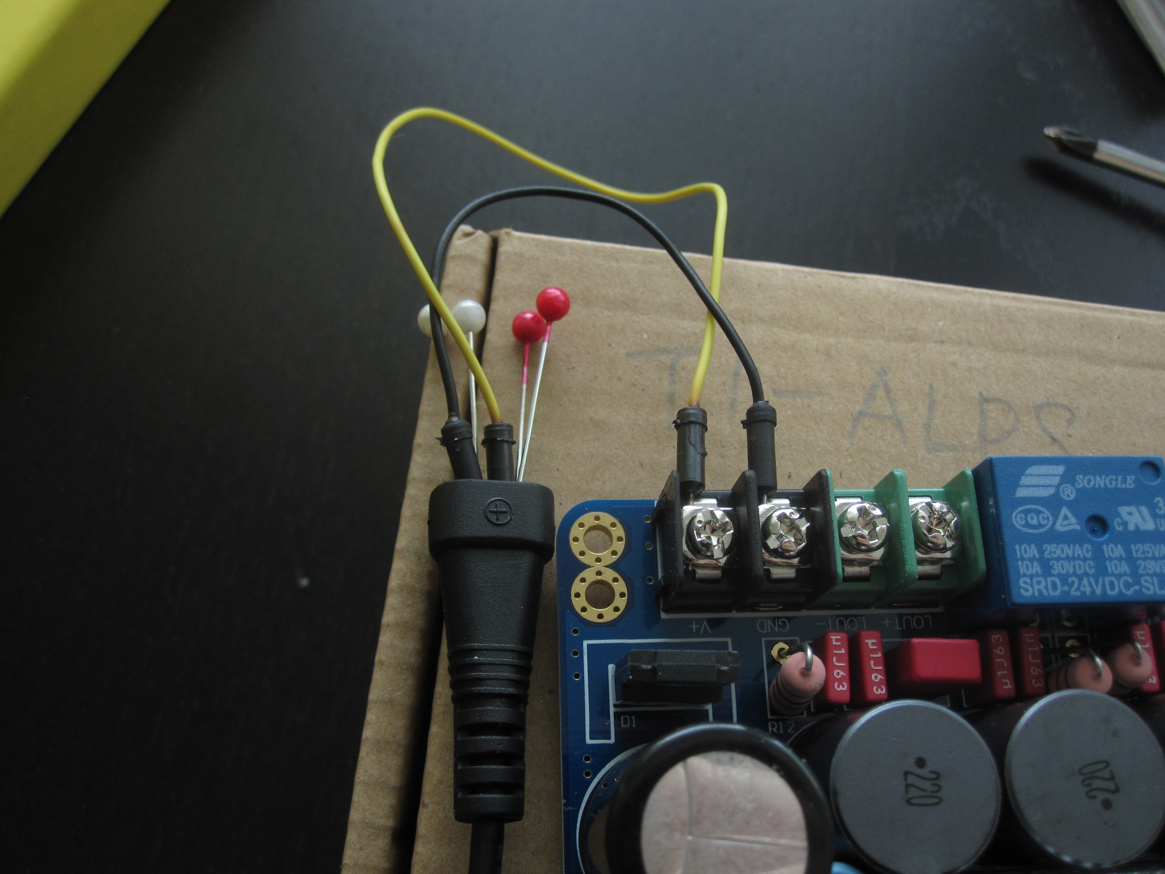
I was just about to clamp aligator clips onto the contact areas of a 3.5 mm plug when I took a step back and came to my senses. I promptly tripped over to Kjell & Co and picked up a proper power supply cable and a 3.5 mm terminal block.
Smoke test
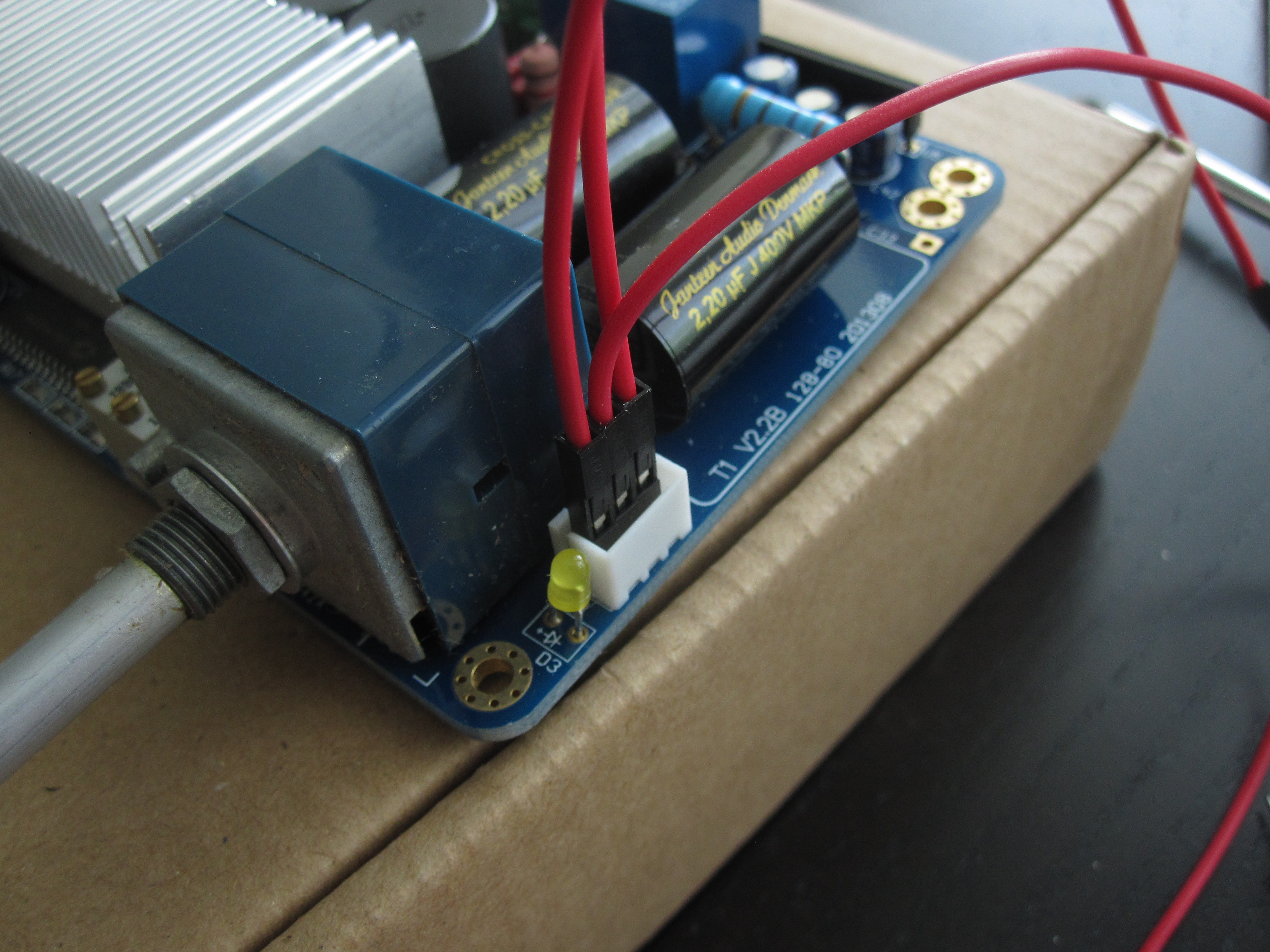
Here is the amplifier completely wired up to my speakers and input source:
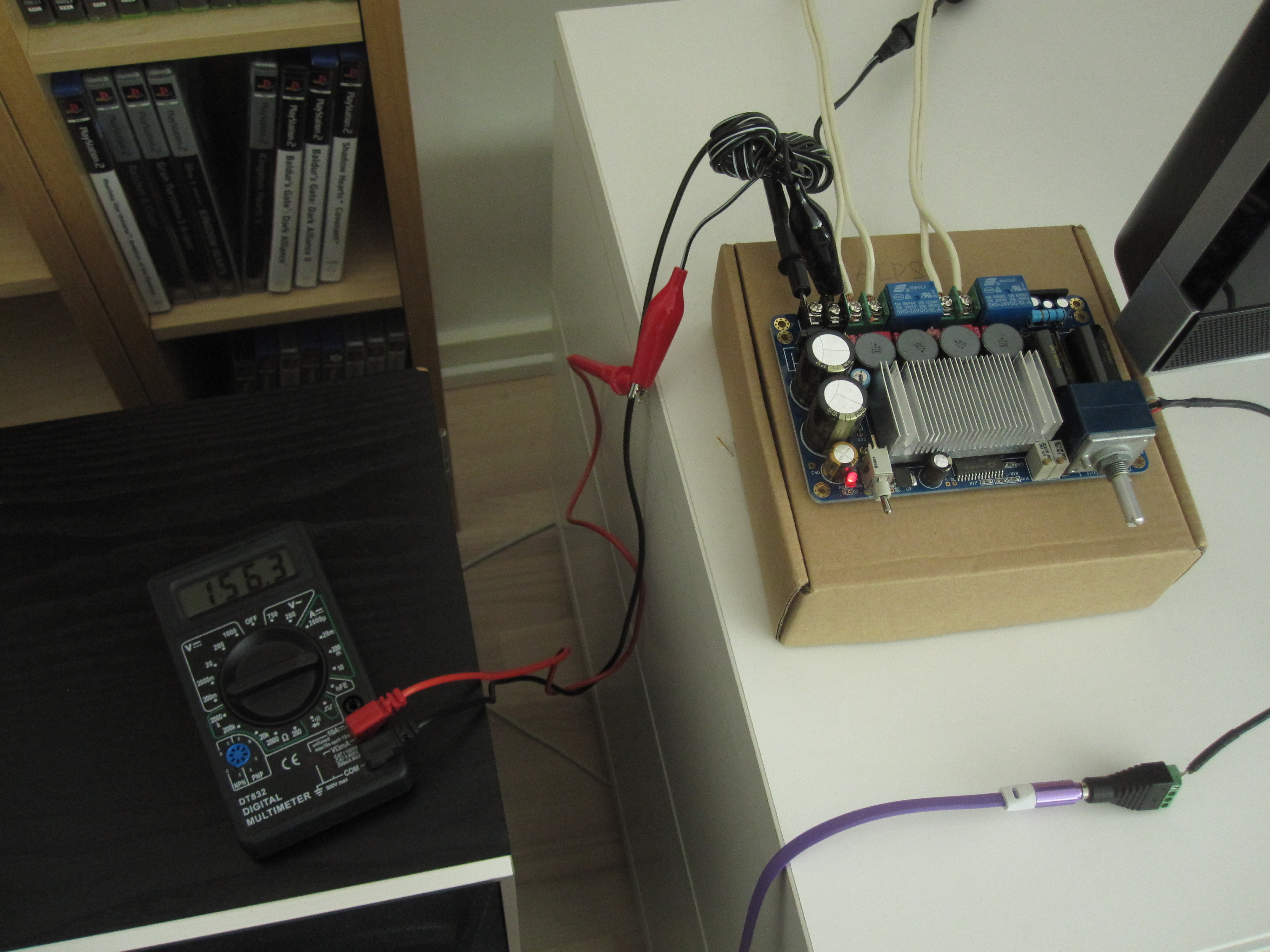
I checked and double-checked all connectors before powering it up for the first smoke test. The red power indicator turned on immediately. After a second or two the yellow happiness indicator turned on and there was a click as the output relays engaged. So far so good.
Playing a song on the input source, both speaker outputs worked and sounded well. I don't have any complaints on the audio quality. The volume control felt smooth and sturdy.
I didn't measure the DC output offset. According to the manual the DC offset should already be adjusted at the factory, and if I'm to measure single digit millivolts with any accuracy I'll probably need a better multimeter than my cheap one anyway.
The amperemeter connected to the 24 V power supply secondary showed about 155-160 mA with the volume turned all the way down to zero. As I turned the volume up to "uncomfortably but not ear-shatteringly loud" the current approached 200 mA, which is less than 5 W. So I'm confident that this power supply will do just fine for this project.
In the next segment I'll cover building an enclosure for the amp.